Optimized Design of Silica Bricks for the Upper Wall of the Regenerator Chamber of a Glass Melting Furnace
The regenerator in a glass melting furnace is the core of its waste heat recovery system. It stores the high-temperature heat from the flue gas and uses it to preheat the combustion air, directly determining the overall energy consumption of the furnace. The upper wall of the regenerator is precisely the most vulnerable “aortic wall” within this heart.
Operating Conditions of the Upper Wall of the Glass Melting Furnace Regenerator
The upper wall of the glass melting furnace regenerator constantly endures the scouring of high-temperature flue gas (1450–1550℃), periodic rapid heating and cooling, and continuous chemical corrosion from alkali metal vapors, while also bearing the entire structural load of the upper lattice structure. There’s an unwritten rule in the industry: 80% of the failures in a furnace’s regenerator occur in the upper wall.
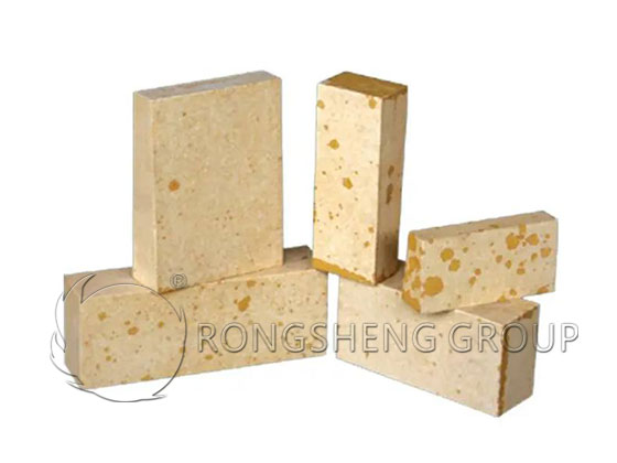
If the silica bricks in the upper section wall of the regenerator experience cracking, peeling, bulging, or collapse, it can lead to anything from minor issues like flue gas short-circuiting and a sharp drop in thermal efficiency, to more serious problems like grid collapse and forced premature cold repairs of the entire kiln, resulting in losses of tens of millions of yuan in a single instance. Many companies invest heavily in optimizing the pool walls and arches, neglecting the design flaws of the silica bricks in the upper section wall of the regenerator, ultimately limiting the kiln’s operational lifespan due to its “weakest link.”
Rongsheng Refractory Factory, a manufacturer of regenerator refractories, will systematically analyze the optimization design logic of silica bricks in the upper section wall of the regenerator from five dimensions: material properties, operational pain points, structural design, masonry details, and thermal matching. They will provide a feasible engineering optimization solution to transform the upper section wall from a “vulnerable component” into the most durable high-temperature barrier in the kiln.
Why do Silica Bricks in the Upper Wall of a Regenerator “Fail Quickly”?
Before optimization, it’s crucial to understand the four core mechanisms of silica brick failure in the upper wall—all optimization designs are essentially aimed at addressing these four destructive factors.
1.1 The Hidden Danger of High-Temperature Creep
Although silica bricks have a load softening temperature as high as 1620℃, under long-term high-temperature loads above 1450℃, they undergo slow plastic deformation, commonly known in the industry as “creep.” The top of the upper wall of the regenerator is directly exposed to flue gas at around 1500℃ and bears the entire weight of the several-meter-high grid structure above. After long-term operation, the wall is prone to overall subsidence, top bulging deformation, and in severe cases, it can directly collapse the underlying structure.
Ordinary silica bricks can exhibit a creep rate of 0.5%/100h at 1550℃ and a load of 0.2MPa, and visible wall deformation may appear after only 3 years of operation.
1.2 Thermal Shock Cracking
The regenerator operates on a cyclical switching pattern: a “flue gas-air” switch every 30 minutes causes the surface temperature of the silica bricks in the upper wall to fluctuate drastically between 1300 and 1500℃. Each sudden temperature change generates enormous thermal stress within the brick. Ordinary silica bricks have a thermal shock resistance of only 10-15 cycles (1100℃ water cooling), inevitably leading to numerous microcracks under long-term cycling. As these cracks propagate, brick spalling and wall cracking occur.
1.3 Alkali Erosion and Penetration
The flue gas from the glass melting furnace carries large amounts of alkaline oxide vapors such as Na₂O and K₂O. These alkaline vapors penetrate the silica bricks through their pores, reacting with SiO₂ to form low-melting-point sodium silicate and potassium silicate. These low-melting-point substances are molten at high temperatures, not only dissolving the brick’s framework but also causing significant volume expansion upon cooling, “cracking” the silica bricks from the inside—a phenomenon commonly referred to in the industry as “alkali expansion.” The alkali vapor concentration in ultra-clear glass kilns is more than 30% higher than that in ordinary float glass kilns, and the alkali corrosion rate of the upper wall silica bricks is accelerated several times over.
1.4 Mechanical Loss Due to Flue Gas Erosion
High-speed flowing, high-temperature flue gas, carrying fly ash and refractory debris, continuously erodes the inner surface of the upper wall at speeds of several meters per second. Under long-term erosion, grooves are “eaten” into the surface of the silica bricks, causing rapid thinning in localized areas and ultimately forming leakage channels.
The failure of the upper wall silica bricks is the result of a quadruple destructive effect: high-temperature creep, thermal shock cracking, alkali corrosion penetration, and flue gas erosion. Optimization design cannot focus on just one point; all four aspects must be addressed simultaneously.
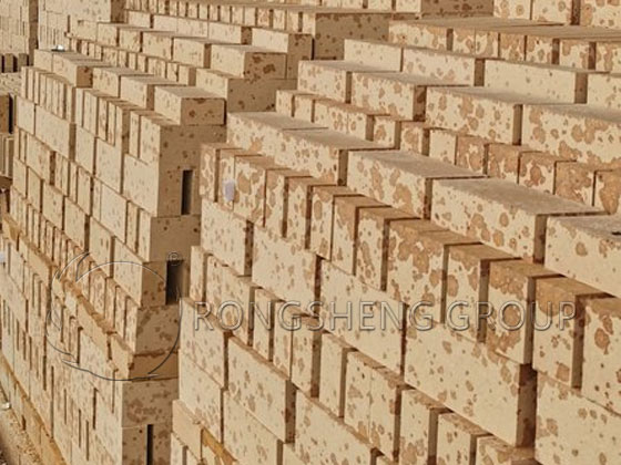
Material-Level Optimization: Enhancing Silica Brick Performance from the Source
The first step in optimization is to start with the silica brick’s formulation and production process, beginning with the raw materials to prepare for improved performance.
2.1 Raw Material Gradation Optimization: Reducing Creep
Traditional silica bricks often use a simple “coarse particles + fine powder” ratio. The optimized gradation adopts a “three-stage particle size distribution system”:
- Coarse particles (1- 3 mm) account for 40%, forming the skeletal structure of the brick and resisting high-temperature creep.
- Medium particles (0.1- 1 mm) account for 30%, filling the voids between coarse particles and increasing density.
- Fine powder (< 0.1 mm) accounts for 30%, ensuring sufficient reaction during sintering and reducing porosity.
With this gradation, the apparent porosity of silica bricks can be reduced from the traditional 22% to below 18%. Creep rate at 1550℃ and 0.2MPa is reduced by more than 60%, significantly improving high-temperature deformation resistance.
2.2 Mineral Phase Composition Control
The key mineral phases for improving the thermal shock stability of silica bricks are tridymite, cristobalite, and residual quartz. In optimized design, a small amount of mineralizer (such as Fe₂O₃ and CaO with trace proportions) is added to promote the full conversion of quartz to tridymite, controlling the residual quartz content below 0.5%.
Residual quartz is the “culprit” of thermal shock cracking in silica bricks—it undergoes a crystal transformation at 573℃, accompanied by a huge volumetric abrupt change. After the residual quartz content is reduced to below 0.5%, the thermal shock stability of the silica bricks can be increased from 10 cycles to over 25 cycles, perfectly adapting to the periodic reversal conditions of the regenerator.
2.3 Alkali Erosion Resistance Modification
During the production process of silica bricks, a small amount of Al₂O₃ and ZrO₂ micropowder is introduced to form a composite phase structure inside the brick body:
- Al₂O₃ reacts with alkali vapor to generate high-melting-point aluminosilicates, preventing further penetration of alkali ions. ZrO₂ particles, acting as the second phase, pinnify crack propagation paths and simultaneously enhance the chemical stability of the brick.
- The modified silica brick, after 100 hours of exposure to alkaline vapor at 1300℃, exhibits an erosion depth only one-third that of ordinary silica bricks, completely solving the long-term alkaline corrosion problem of upper walls.
The optimized silica bricks specifically designed for upper walls show improvements in all core performance indicators.
Structural Optimization: Enhancing Wall Stress and Lifespan
Material upgrades are just the foundation; optimized structural design is essential to maximizing the performance of silica bricks.
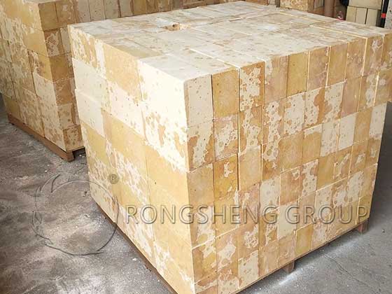
3.1 Segmented Wall Design: A Clever Approach to Releasing Thermal Stress
Traditional upper walls are continuous single sections. Under high temperatures, the entire wall expands without release space, easily leading to overall bulging and deformation. The optimized “segmented wall” design incorporates expansion joints every 2-3 meters, dividing the entire wall into multiple independent wall units:
- The expansion joint width is set at 8- 12 mm, filled with compressible high-alumina refractory fibers.
- The expansion joints are positioned to avoid the main flue gas scouring channel, preventing direct flue gas leakage.
- Each wall unit independently bears the load of the upper grid structure, avoiding stress concentration in localized areas.
With this design, the wall’s thermal expansion displacement can be completely released, resulting in virtually no overall bulging or deformation during operation.
3.2 Staggered Joint Masonry: Making the Wall a “Single Brick”
Traditionally, upper walls often use a simple straight-lay method, with brick joints aligned vertically, easily becoming a “green channel” for crack propagation. The optimized “fully staggered joint masonry”:
- The vertical joints of the upper and lower layers of bricks are completely staggered, with a stagger distance of no less than 1/3 of the brick length.
- Adjacent three bricks form an interlocking structure, preventing a single brick crack from causing the entire wall to crack through.
- All brick joint thickness is strictly controlled to 1- 1.5 mm, and is fully filled with silica refractory mortar, leaving no cavities.
This wall structure has an overall strength 40% higher than the traditional straight-lay method, and its crack resistance is significantly enhanced.
3.3 Localized Structural Reinforcement: Precise Upgrades in “High-Risk Zones”
The upper wall has several “high-risk zones” most severely affected by erosion, requiring targeted structural reinforcement:
- Opposite the flue gas inlet: This is the area most intensely eroded by flue gas. Thicker silica bricks are used, increasing the brick thickness from the standard 230mm to 345mm. A rounded transition structure is also incorporated on the fire-facing side of the bricks to reduce the direct erosive force of the flue gas.
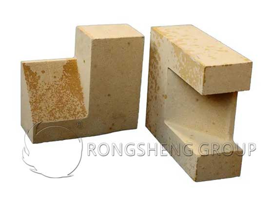
- Wall-to-arch junction: This location experiences the greatest temperature difference and highest stress concentration. Irregularly shaped silica bricks are used for the transition, avoiding stress concentration caused by right-angle intersections.
Around the manhole: The area around the opening is a structural weak point. Arched silica bricks are used for reinforcement to distribute stress around the opening and prevent cracking and deformation.
3.4 Layered Load-Bearing Structure: Distributing Weight
Traditionally, the entire load of the upper wall is borne by the lower wall. Under prolonged high temperatures, this can easily lead to the lower bricks being crushed. The optimized “layered load-bearing” design:
- A load-bearing steel support plate is installed in the middle of the upper wall section, directly transferring part of the load from the upper lattice structure to the steel frame of the heat storage chamber, preventing it from acting on the wall itself.
- An insulation layer is installed between the steel support plate and the silica bricks to prevent high-temperature deformation of the steel support plate.
The wall only bears its own weight, significantly reducing the long-term load on the silica bricks and fundamentally preventing wall settlement caused by high-temperature creep.
Thermal Compatibility Optimization: Making the Working Environment of Silica Bricks More “Friendly”
Even the best silica brick design cannot achieve optimal performance if it is mismatched with the thermal regime.
4.1 Temperature Field Uniformity Design: Eliminating Local “Hot Spots”
Excessively high local temperatures in the upper wall are a core cause of rapid creep failure in silica bricks. In the optimized design, by adjusting the flue gas distributor at the top of the regenerator, the flue gas entering the regenerator is evenly distributed along the length of the wall:
- This avoids excessively high flue gas velocity and temperatures exceeding 1550℃ in localized areas.
The operating temperature of the silica bricks in the upper wall is controlled within the optimal range of 1450–1500℃, ensuring heat storage efficiency without exceeding the long-term safe operating temperature of the silica bricks.
4.2 Reversing Cycle Optimization: Reducing Thermal Shock
The traditional reversing cycle of 30 minutes results in excessively frequent temperature fluctuations. The optimized “variable cycle reversing” cycle:
- During the stable operation phase of the kiln, the reversing cycle is extended to 45 minutes, reducing the frequency of temperature alternation.
- The transition time for each reversal was extended from 3 seconds to 5 seconds to avoid severe impacts from sudden temperature changes on the silica bricks.
Actual measurement data shows that after optimizing the reversal system, the surface temperature fluctuation of the silica bricks in the upper section of the wall decreased from 200℃ to 120℃, thermal stress decreased by 40%, and the risk of thermal shock cracking of the silica bricks was significantly reduced.
4.3 Micro-positive pressure operation control: reducing alkali vapor penetration
Long-term negative pressure operation of the heat storage chamber leads to the infiltration of a large amount of cold air from the outside, while simultaneously accelerating the penetration of alkali vapor into the silica bricks. Optimized micro-positive pressure control:
- The pressure in the upper section of the heat storage chamber is controlled within a micro-positive pressure range of 0–10 Pa.
- This prevents the leakage of large amounts of high-temperature flue gas and also prevents the bidirectional penetration of cold air and alkali vapor.
The alkali corrosion rate of the silica bricks is reduced by more than 50%.
Details Easily Overlooked in Project Implementation
Many optimized designs look perfect on paper, but the actual effect is compromised after implementation, often due to problems with the details.
5.1 Pre-expansion Treatment Before Laying
Silica bricks undergo crystalline expansion at high temperatures. Before laying, a pre-expansion test must be performed on the silica bricks. Sufficient expansion joints must be reserved based on the measured expansion rate; the values in the standard drawings cannot be completely copied. The expansion rate of silica bricks can vary by up to 0.2% between different batches. Insufficient pre-expansion can easily lead to cracking of the wall.
5.2 The “Silica Brick-Specific Section” of the Kiln Drying Curve
Silica bricks undergo drastic crystalline transformations in two temperature ranges: 200–300℃ and 573℃. During the kiln drying process, the heating rate in these two ranges must be strictly controlled to ≤10℃/h. Rapid heating is absolutely prohibited; otherwise, the silica bricks will crack extensively. Many kiln upper walls crack within a year of operation, often due to excessively rapid heating during the kiln drying stage.
5.3 Online Monitoring System Support
Thermocouples are pre-embedded inside the silica bricks of the upper section of the wall to monitor the temperature distribution of the bricks in real time. Simultaneously, an infrared thermal imaging scanning system is installed on the outside of the wall:
- Areas with abnormally high temperatures indicate the locations of silica brick erosion and thinning.
- Early signs of wall failure can be detected 6-12 months in advance, allowing for timely intervention.
Verified Results of Optimization: Visible Benefits
A 600t/d ultra-white float glass furnace, after adopting the above-mentioned optimized design for silica bricks, showed the following after 5 years of operation:
The maximum erosion depth of the silica bricks in the upper wall was only 25mm, far lower than the 80mm of the traditional design.
The waste heat recovery efficiency of the regenerator was improved by 11%, and the fuel consumption of the entire furnace was reduced by 6.5%.
No bulging or cracking occurred in the upper wall, extending the expected safe lifespan from the traditional 8 years to over 12 years.
Premature cold repairs were avoided, directly generating economic benefits exceeding 20 million yuan.
Summary of the Optimized Design of Silica Bricks in the Upper Wall of the Regenerator Chamber of a Glass Melting Furnace
The optimized design of silica bricks in the upper wall of the regenerator chamber of a glass melting furnace is not simply about “changing to better bricks,” but a systematic upgrade across the entire chain, from material formulation and structural design to thermal matching and operation and maintenance management. Many companies focus on the “star components” like the tank walls and the main arch, neglecting the “silent weak link”—the upper wall of the regenerator. When you optimize every detail of the silica bricks in the upper wall, you’ll find that the furnace’s thermal efficiency increases, energy consumption decreases, and the overall lifespan naturally extends. For a glass melting furnace, true longevity isn’t about the ultimate excellence of a single part, but about perfecting every seemingly insignificant detail.